TinyKart
Autonomous RC NavigationAn RC car retrofitted with a LiDAR sensor and STM32 microcontroller to navigate a closed circuit track fully autonomously. The car reads 180° distance data in real time, identifies the widest open gap, and drives toward it — no human input required once running. Built for the Intelligent Systems Club's semester-long autonomous vehicle competition, TinyKart was the only entry to finish and race — becoming the blueprint future members built from.
Every iteration of the main loop follows a strict pipeline: receive a LiDAR packet over UART via DMA, validate it with a CRC8 checksum, parse the 12 distance readings into the 180° array, then run the navigation algorithm and write steering and speed out as PWM signals to the servo and ESC.
When I joined, the team was working on the widest-gap algorithm but the car wasn't turning. The LiDAR
was mounted with its 0° facing the front of the car, so the front-facing arc spans 270°–360° and
0°–90°. FillArray remaps this into a flat array where index 0 is 90° to
the left, index 90 is straight ahead, and index 180 is 90° to the right.
The code mapped angles 0°–90° and 270°–360° into lidar_180[], but had a critical edge case. Each packet contains 12 distance
readings approximately 1° apart, so a packet starting at 259° has its 12th reading land at roughly
270°. Any packet with a start angle between 259° and 270° was silently dropped — even
though part of it contained valid data that crossed the 270° boundary into the mapped range.
It was highly unlikely for a packet to start exactly at 270°, so index 0 was almost never filled.
Since angle_count never reached 180, FindBiggestGap was never called — the car drove straight at the default
steering value with no autonomous correction at all.
Angle_Index >= 259, the code calculates how many readings to skip at the start
of the packet and begins filling from index 0, recovering the data that was previously lost.
I also used the onboard LED (HAL_GPIO_TogglePin) to confirm the fill loop
was completing correctly — a simple but effective debug technique without a full debugger.
void FillArray(LiDARFrameTypeDef lf)
{
  uint16_t Angle_Index = lf.start_angle;

  if (Angle_Index <= 90 || Angle_Index >= 259)
  {
    uint8_t i = 0;

    if (Angle_Index >= 259)
    {
      if (Angle_Index < 270)
      {
        // Packet starts mid-window: skip readings
        // before 270°, start filling from index 0
        i = 270 - Angle_Index;
        Angle_Index = 0;
      }
      else
      {
        Angle_Index -= 270;
      }
    }
    else
    {
      Angle_Index += 90;
    }

    for (; i < 12 && Angle_Index <= 180; i++, Angle_Index++)
    {
      if (lidar_180[Angle_Index] == 1)
      {
        lidar_180[Angle_Index] = lf.distance[i];
        angle_count++;
      }
    }
  }
}
Once lidar_180[] is filled, CreateBubble finds
the closest obstacle and zeros out a window of readings around it. By removing those indices from
consideration, the midpoint of any gap that gets selected is pushed further away from the nearest
obstacle — naturally building in clearance without any explicit buffer logic.
FindBiggestGap then scans the array for the longest contiguous run of
readings above a distance threshold (minimum_gap). The center of that run
becomes the target steering direction, mapped linearly to a PWM value for the servo.
Speed is also scaled dynamically — a linear function of the average forward distance means the car slows down as obstacles approach and accelerates in open straights.
// Scale speed linearly to forward distance
// slower near obstacles, faster in open space
if (AvgDist <= 5000 || AvgDist >= 1000)
{
  speed = floor(0.00075 * AvgDist + 159.25);
}
Key parameters were tuned per-track. A larger space needs a higher minimum_gap threshold and wider steering window; a tighter track needs more
sensitivity to smaller gaps and a narrower steering range.
minimum_gapBefore the widest-gap algorithm, the team implemented a simpler wall-following approach. Rather than scanning the full 180° for open space, the car maintained a fixed lateral distance from one wall and followed its contour around the track.
Wall following works reliably on simple oval or rectangular tracks but breaks down at intersections, dead ends, or any geometry where the reference wall disappears. The widest-gap approach generalizes better to arbitrary track shapes — which is why the team moved to it.
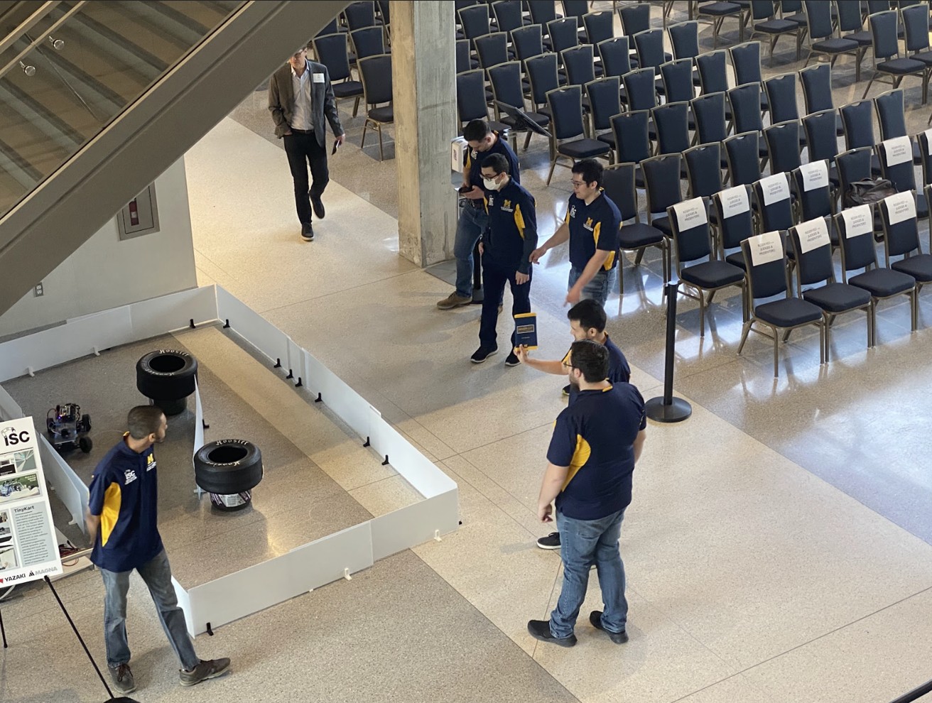
The senior design showcase was held in the university's ELB building atrium. Unfortunately no recording of the senior design run was captured. The GIFs below show the car during lab runs, and the team photo is from the showcase itself.
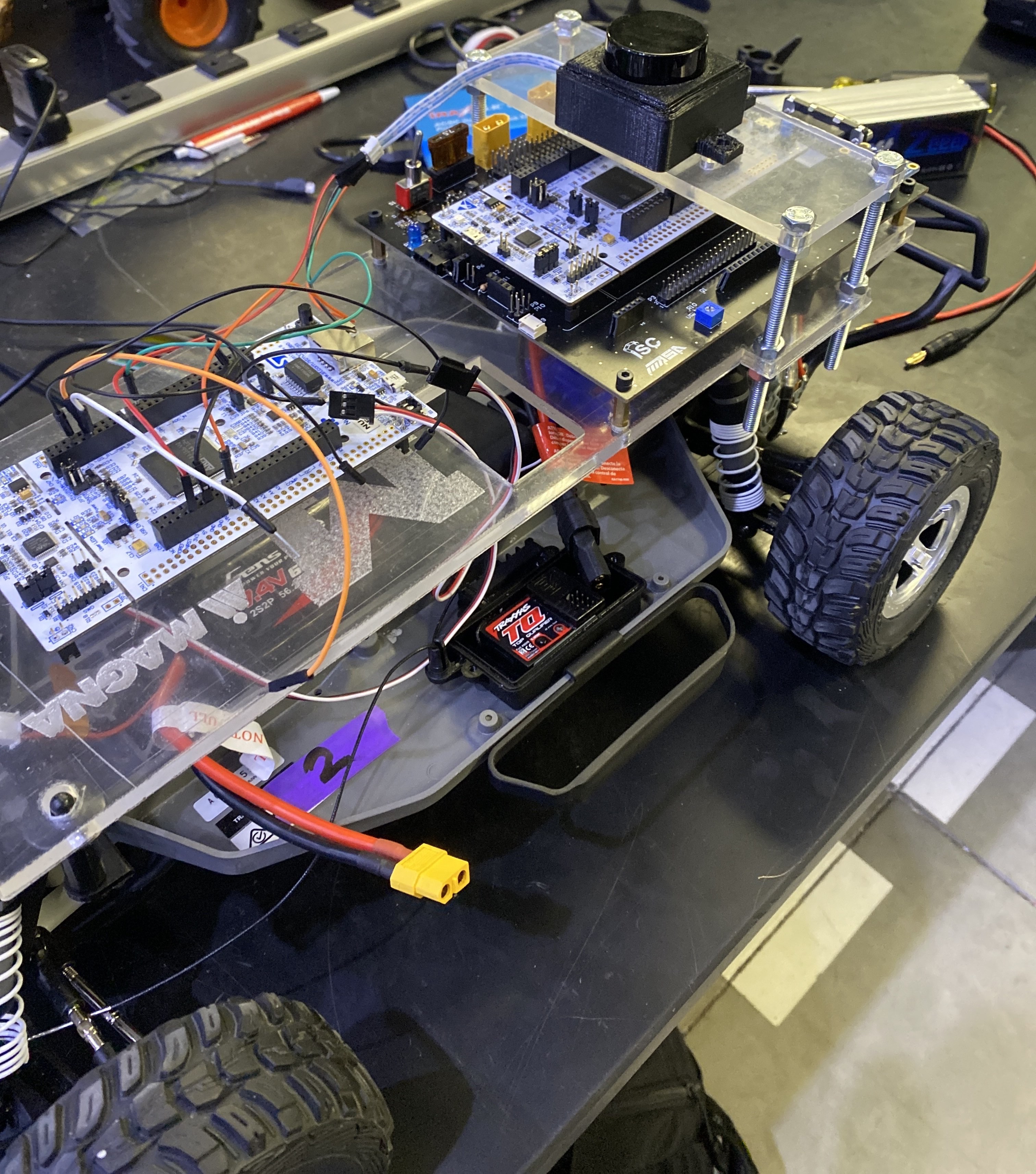
The base vehicle is a Traxxas RC car with an off-the-shelf ESC and servo already in place. The electronics stack was mounted on a custom 3D-printed and laser-cut acrylic platform bolted to the chassis.
The LD06 LiDAR sits on the top tier, giving it a clear 360° field of view above the body. The STM32 development board sits below it on the middle tier. A separate motor driver board occupies the lower shelf. Power comes from a LiPo battery pack wired through a XT60 connector at the front.
The servo and ESC are controlled via PWM from the STM32's TIM1 peripheral — CCR1 for motor speed, CCR2 for steering angle. The
photo shows one iteration of the hardware build — the setup evolved throughout the semester as the team
refined the mounting and wiring.